Category: Asset Protection Economics

  • The Strategic Architecture of Pipeline Blasting: A Cost-Conscious Approach

    The Strategic Architecture of Pipeline Blasting: A Cost-Conscious Approach

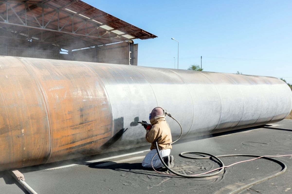
    How to plan pipeline blasting on a budget industrial maintenance and infrastructure development rely heavily on the integrity of subterranean and surface transport systems. Pipeline blasting—the process of removing industrial coatings, oxidation, corrosion, and scale to prepare surfaces for inspection or recoating—is a critical path activity. When resource constraints are tight, the margin for error vanishes. Successful project execution requires a shift from viewing blasting as a commodity service to understanding it as a precise engineering discipline where systemic inefficiencies represent the greatest drain on capital.

    This document serves as a comprehensive reference for stakeholders managing industrial asset integrity. It dissects the variables governing cost-effective surface preparation, moving beyond simple hourly rate reduction to focus on total cost of ownership, operational uptime, and long-term asset life cycles. Whether managing aging midstream infrastructure or new utility installations, the core challenge remains constant: achieving the required surface profile without compromising environmental compliance, safety standards, or project schedules.

    The following analysis provides the framework for optimizing surface preparation projects. By aligning technical requirements with fiscal discipline, organizations can navigate the complexities of large-scale maintenance while maintaining high standards of quality assurance.

    Understanding “how to plan pipeline blasting on a budget”

    The phrase “how to plan pipeline blasting on a budget” is frequently misinterpreted as a directive to seek the cheapest abrasive or the lowest daily labor rate. This is a fundamental misunderstanding that often leads to catastrophic cost overruns. In the context of industrial engineering, budgetary planning is an exercise in resource optimization rather than mere cost cutting. Attempting to reduce upfront expenditures by selecting suboptimal blast media, bypassing comprehensive containment, or ignoring the specific substrate profile requirements often triggers a chain reaction of failures: premature coating breakdown, regulatory fines, and the need for expensive secondary mobilization.

    True fiscal discipline in this sector involves a rigorous focus on throughput and quality control. When planning, the focus must shift to the “cost-per-square-foot” of compliant surface area. If a low-cost media requires triple the pass rate to achieve a NACE or SSPC standard, the labor costs will inevitably erode any savings gained from the abrasive purchase. Furthermore, understanding the interaction between the existing coating system and the underlying metal is essential. Misjudging this leads to “over-blasting,” which wastes media, damages the substrate, and significantly increases waste disposal costs. Mastering how to plan pipeline blasting on a budget requires the project manager to view the blasting operation as a singular component of a larger protective system, where precision in the initial phase dictates the durability and cost-efficiency of the entire maintenance cycle.

    The Evolution of Industrial Surface Preparation

    How to plan pipeline blasting on a budget historically, pipeline maintenance was dictated by rudimentary mechanical cleaning and the localized application of high-energy abrasive media. The evolution from manual wire-brushing to sophisticated closed-circuit blasting systems has been driven by the dual pressures of environmental regulation and the need for extended asset life. As pipelines have aged, the materials used in coating—ranging from legacy coal tar epoxies to modern plural-component polyureas—have become more resilient, necessitating more advanced removal techniques.

    This systemic evolution has moved the industry toward “precision blasting.” Rather than relying on brute force, modern protocols prioritize the selection of media—whether crushed glass, garnet, or recycled steel grit—that can surgically remove contaminants without inducing a damaging anchor profile. This shift recognizes that the physical structure of the pipe is the most expensive component in the equation. Protecting the pipe’s metallurgy while removing the protective barrier is the central tension in all modern pipeline maintenance strategies.

    Conceptual Frameworks and Mental Models How To Plan Pipeline Blasting On A Budget

    To effectively plan for complex industrial projects, managers should utilize specific mental models that isolate variables and clarify objectives:

    • The Throughput-Quality Matrix: This model maps the relationship between blast speed and surface finish. It forces the manager to identify the “inflection point”—the moment where an increase in speed results in a non-compliant profile.

    • Total Cost of Containment (TCC): This framework accounts for not just the blasting, but the logistical burden of hazardous waste collection, air filtration, and site remediation. Often, the cost of the blast is eclipsed by the cost of the containment.

    • Substrate Preservation Protocol: This model treats the substrate as a finite asset. It prioritizes the use of the softest media capable of doing the work, minimizing the risk of substrate erosion.

    • The Pareto of Failure: A diagnostic model used to categorize previous failures. In most blasting projects, 80% of issues stem from 20% of the variables (typically humidity control, air volume/pressure, or nozzle-to-surface geometry).

    Technical Categorization and Trade-offs

    Selecting the correct media and method is the primary driver of project variance. The following table summarizes the trade-offs between common approaches.

    Category Typical Media Strengths Weaknesses
    Recyclable Abrasive Steel Grit High efficiency, consistent profile High initial equipment setup
    Expendable Abrasive Garnet Minimal setup, high portability High disposal cost, dust management
    Hydro-Blasting High-Pressure Water Zero dust, environmental compliance Requires complex drying/inhibitor steps
    Mechanical Removal Power Tools (SSPC-SP 3) Low footprint, no media waste Extremely labor intensive

    Realistic decision logic dictates that projects involving long linear miles of pipe favor high-throughput, recyclable systems, whereas localized maintenance or “spot-blasting” in sensitive environments necessitates more mobile, expendable, or water-based strategies.

    Detailed Real-World Scenarios How To Plan Pipeline Blasting On A Budget

    The Remote Midstream Inspection

    In a remote location with limited power and logistical access, the constraint is mobilization. Using a large, recyclable system is impractical due to energy requirements and transport. The optimized approach is a high-grade expendable abrasive used with a vacuum-recovery unit, minimizing the site footprint while maintaining compliance.

    High-Density Urban Infrastructure

    When working near residential areas, containment of dust and noise is the primary risk. The decision must favor wet-blasting or vacuum-shrouded systems. While the hourly operational cost is higher, the “cost” of potential litigation or public nuisance claims is effectively mitigated.

    Legacy Coating Removal

    Older pipelines coated with hazardous materials (e.g., lead-based paints) change the cost equation entirely. The planning focus moves to hazmat handling and specialized PPE. Ignoring these regulatory costs in the budget is a common failure mode that creates massive mid-project financial strain.

    Precision Pipeline Repair

    For short segments requiring specific surface profiles for high-performance coatings, the budget must prioritize dwell time and nozzle angle. Here, the use of automated, rail-mounted blasting heads ensures consistency, reducing the risk of re-work—which is the most common cause of budget overruns.

    Planning, Cost, and Resource Dynamics

    The primary error in budgeting is failing to account for indirect costs. When considering how to plan pipeline blasting on a budget, managers often forget to factor in weather delays, equipment depreciation, and the hidden cost of “down-time” during air compressor refueling or nozzle replacement.

    Resource Category Cost Variability Influence on Project Success
    Media Procurement Low to Medium High (affects rate of cleaning)
    Equipment Rentals Medium to High Moderate (affects schedule duration)
    Waste Management High Extreme (potential for fines/logistics)
    Labor (Specialized) High Critical (determines re-work frequency)

    Budgetary success is rarely achieved by minimizing these individual lines; rather, it is found by optimizing the ratio between them to compress the overall project timeline.

    Tools, Strategies, and Support Systems How To Plan Pipeline Blasting On A Audget

    1. Air Quality Monitoring: Essential for avoiding regulatory shutdown.

    2. Surface Profile Gauges: Non-negotiable for ensuring compliance with coating manufacturers’ specifications.

    3. Vacuum-Shrouded Nozzles: Significantly reduces the volume of media required by enabling reuse.

    4. Real-Time Humidity Sensors: Prevents the rapid flash rust that necessitates an immediate (and expensive) re-blast.

    5. Multi-Stage Filtration Systems: Essential for meeting local air quality standards, particularly in populated areas.

    6. Modular Compressor Rigs: Allows for scaling air volume based on the specific blast head, optimizing fuel consumption.

    Risk Landscape and Failure Modes

    The failure to maintain an appropriate anchor profile is the most common technical error. If the profile is too shallow, the coating lacks mechanical interlock; if it is too deep, the “peaks” of the steel are exposed, leading to localized corrosion cells. Both scenarios result in a failed project that requires premature maintenance. Furthermore, operator fatigue is a significant, often overlooked, risk. Blasting is physically and mentally demanding; maintaining quality control requires rigorous shift rotation and oversight to prevent “coasting,” where operators reduce the blast intensity to save effort.

    Governance, Maintenance, and Long-Term Adaptation How To Plan Pipeline Blasting On A Budget

    Governance must include a “Hold-Point” system. After every stage of the project, a supervisor must sign off on the surface quality, containment status, and waste volume. These hold points act as circuit breakers, preventing a systemic issue (like a miscalibrated compressor) from affecting the entire pipeline length.

    Adaptation is equally important. If the initial performance metrics indicate a higher-than-anticipated level of substrate degradation, the plan must trigger an immediate review of the media grade. Attempting to force the original plan onto a changing reality is a recipe for budget exhaustion.

    Measurement, Tracking, and Evaluation

    Effective tracking moves beyond daily logs. Managers should employ:

    • Leading Indicators: Media consumption per linear foot, nozzle pressure stability, and ambient relative humidity.

    • Lagging Indicators: Total square feet prepared, waste volume per unit area, and coating adhesion test results.

    • Documentation Example: Maintain a “Blast Log” that links specific weather conditions and media types to the final surface profile. This data provides the blueprint for future projects, allowing for even tighter cost control in subsequent cycles.

    Common Misconceptions and Oversimplifications How To Plan Pipeline Blasting On A Budget

    • “Higher air pressure equals better results”: Often, higher pressure simply shatters the media faster, creating more dust and less effective impact.

    • “Any media is interchangeable”: The hardness of the media must be tuned to the hardness of the existing scale. Using an overly hard media on a soft pipe surface is a primary cause of substrate damage.

    • “Budgeting should happen at the bid stage”: Budgeting for blasting is an ongoing process that requires adjustment as subsurface conditions are discovered during the removal of the old coating.

    • “Surface prep doesn’t require specialized training”: The lack of certified blasting technicians is a major source of project inefficiency and health and safety risk.

    Conclusion

    Understanding how to plan pipeline blasting on a budget is fundamentally about the synthesis of logistics, material science, and disciplined oversight. The most effective managers recognize that the cheapest path is rarely the most economical. Instead, they focus on the reliability of the system, the protection of the asset, and the minimization of waste. By moving away from reactive cost-cutting and toward a framework of controlled, high-throughput preparation, organizations can ensure that their pipeline infrastructure remains both structurally sound and fiscally viable. Success in this field requires the patience to look beyond the immediate cost and the intellectual honesty to adjust the strategy when conditions deviate from the initial projection.

  • Electrochemical Sovereignty: A Technical Guide to Mitigating Bimetallic Degradation

    Electrochemical Sovereignty: A Technical Guide to Mitigating Bimetallic Degradation

    How to avoid galvanic corrosion risks galvanic corrosion—the silent, electrochemical disintegration of metal—represents one of the most insidious threats to structural integrity in modern engineering. It is a fundamental thermodynamic reality: when two dissimilar metals are placed in electrical contact within a common electrolyte, the less noble material will sacrifice its structural mass to protect the more noble one. This is not a failure of maintenance, but a manifestation of basic chemistry. Understanding the mechanisms of this process is the first step toward effective asset protection.

    The challenge, however, is that industrial environments are rarely static or isolated. Complex assemblies, varying humidity levels, and the ubiquity of conductive fluids create unpredictable pathways for electron flow. Engineering for longevity requires a shift from reactive repair to an architectural approach that treats the electrical isolation of components as a core design requirement.

    This article provides an authoritative deep dive into the engineering of galvanic mitigation. It is intended for structural engineers, asset managers, and technical planners who recognize that the cost of inaction—structural failure—is catastrophic. By focusing on systemic prevention rather than symptomatic repair, we can design environments that resist the unrelenting forces of electrochemical degradation.

    Understanding “how to avoid galvanic corrosion risks”

    The phrase “how to avoid galvanic corrosion risks” is frequently treated as a checklist of simple material pairings, but this is a dangerous reduction. In practice, avoiding these risks requires a holistic understanding of the “galvanic triad”: the anode, the cathode, and the electrolyte. If any of these three elements are present and in play, the risk of corrosion is non-zero. A common misunderstanding is the belief that using two metals close together on the galvanic scale eliminates the risk. While it reduces the potential difference, it does not stop the process if the environment (electrolyte) is sufficiently conductive.

    Oversimplification in this field often leads to “design debt”—where a structure is finalized, only to be discovered as a giant battery waiting for moisture. To truly master how to avoid galvanic corrosion risks, one must evaluate the surface area ratio of the two metals: a large cathodic surface area coupled with a small anodic surface area (like stainless steel bolts in an aluminum plate) will lead to rapid, localized failure of the aluminum. Therefore, the strategy must account for surface area, distance between connections, and the availability of moisture, rather than just the choice of materials.

    Deep Contextual Background: The Evolution of Electrochemical Mitigation

    How to avoid galvanic corrosion risks the historical progression of mitigation techniques has moved from primitive “insulating washers” to sophisticated dielectric coating systems and cathodic protection protocols. Early approaches were reactive, relying on mechanical isolation that frequently failed due to vibration or environmental degradation. The development of modern polymers and ceramic-based barriers has fundamentally altered the landscape, allowing for the precise management of electrical continuity.

    As infrastructure becomes more integrated—incorporating sensors, smart controls, and high-performance alloys—the risk of bimetallic corrosion has surged. The industry has shifted from a “materials compatibility” model to a “systemic isolation” model, where the entire assembly is designed as an electrically discontinuous network.

    Conceptual Frameworks and Mental Models How To Avoid Galvanic Corrosion Risks

    To mitigate risk, engineers utilize the following models:

    • The Potential Difference Map: Calculating the open-circuit potential of every junction in an assembly.

    • The Cathode-Anode Area Ratio Model: Identifying the high-risk zones where a small anode is disproportionately vulnerable.

    • The Electrolyte Resistance Model: Assessing the conductivity of the environment to determine the effective “reach” of the galvanic current.

    • The Dielectric Barrier Framework: Designing for multiple, redundant layers of electrical insulation.

    Key Categories, Trade-offs, and Decision Logic

    Mitigation Strategy Mechanism Primary Limitation
    Dielectric Isolation Non-conductive spacers/bushings Mechanical wear; vibration
    Protective Coatings Shielding the surface Prone to scratching/pinholes
    Cathodic Protection Sacrificial anode usage Requires ongoing monitoring
    Material Matching Minimizing potential difference Limits design/material choice
    Environmental Control Eliminating electrolyte High cost; impractical in situ

    Decision Logic: When determining how to avoid galvanic corrosion risks, prioritize the “Passive-Active Hierarchy.” Start by designing passive isolation (dielectrics) into the geometry of the connection. Use active measures (cathodic protection) only when passive isolation cannot be guaranteed due to the structural complexity of the assembly.

    Real-World Scenarios and Failure Modes How To Avoid Galvanic Corrosion Risks

    Coastal Structural Framing

    Stainless steel fasteners in aluminum extrusions. The electrolyte is the salt spray from the ocean. Failure mode: Crevice corrosion beneath the fastener heads. Decision point: Use isolation bushings or specialty coated fasteners that minimize conductivity.

    Submerged Pipeline Junction

    A copper pipe connected to a steel line. The soil is the electrolyte. Failure mode: Accelerated corrosion of the steel due to the larger cathodic area of the copper. Decision point: Use a dielectric flange kit and a dedicated sacrificial anode to protect the steel junction.

    Planning, Cost, and Resource Dynamics

    The economic impact of galvanic failure is often hidden in the “hidden cost of re-work.”

    Element Direct Cost Indirect Cost (Risk)
    Dielectric Washers Low Low (replacement easy)
    Specialized Alloys High Low (long-term durability)
    Sacrificial Anodes Moderate Moderate (maintenance required)
    Remediation Very High Extreme (failure of asset)

    Tools, Strategies, and Support Systems

    1. Potentiometers: Measuring the potential difference between components.

    2. Dielectric Integrity Testers: Ensuring that isolation bushings remain effective.

    3. Conductivity Sensors: Mapping the electrolyte potential in the local environment.

    4. Galvanic Series Tables: Providing the baseline data for all material selections.

    5. Digital Asset Logs: Recording the material specs for every fastener and joint.

    Risk Landscape and Failure Modes How To Avoid Galvanic Corrosion Risks

    Risk in these systems is non-linear and compounding:

    • Crevice Degradation: Moisture gets trapped in a joint, creating a localized, aggressive electrolyte.

    • Service Life Mismatch: An insulating bushing wears out due to heat cycles, causing a latent failure after five years of successful operation.

    Governance, Maintenance, and Long-Term Adaptation

    A robust program involves:

    • Layered Checklists: Verifying insulation at every assembly point.

    • Adjustment Triggers: If moisture levels in the operating environment rise, re-evaluate the electrical isolation protocols.

    • Monitoring Cycles: Annual inspection of “high-risk” zones where moisture pooling is likely.

    Measurement, Tracking, and Evaluation How To Avoid Galvanic Corrosion Risks

    • Leading Indicators: Installation of non-conductive hardware; documentation of material potentials during the design phase.

    • Lagging Indicators: Evidence of oxidation at junction points; loss of continuity resistance.

    • Documentation Example: An electrical isolation map of the structure, identifying every junction and the corresponding isolation method used.

    Common Misconceptions and Oversimplifications

    1. “Stainless steel is immune to corrosion.” It is not; it is simply more noble and can easily act as a cathode, destroying neighboring metals.

    2. “Isolation is always easy.” In high-vibration environments, isolation washers frequently fail.

    3. “Paint covers the risk.” A thin, scratched layer of paint is a liability, not an insurance policy.

    4. “Sacrificial anodes last forever.” They are consumables and require periodic replacement.

    5. “You only need to worry about water.” Even humidity can be enough electrolyte to initiate the circuit.

    Conclusion How To Avoid Galvanic Corrosion Risks

    Mastering how to avoid galvanic corrosion risks is essentially an exercise in maintaining electrochemical autonomy. By designing systems that prioritize dielectric isolation, understanding the material potentials of every component, and accepting the reality of the electrolyte in our environments, engineers can build structures that resist the pull of the galvanic series. The goal is to design an assembly that remains inert and stable, regardless of the environmental challenges it faces. This requires foresight, precise material selection, and a rigorous adherence to the principles of electrical isolation. Through such discipline, we build not just for the present, but for a future free from the silent, structural theft of galvanic degradation.

  • The Mechanics of Separation: An Investigative Analysis of Coating Failure and Remediation

    The Mechanics of Separation: An Investigative Analysis of Coating Failure and Remediation

    How to manage coating delamination coating delamination represents the most critical failure mode in industrial asset management. It is not merely a cosmetic blemish or an aesthetic oversight; it is a structural decoupling where the engineered barrier loses its adhesion to the substrate, rendering the underlying material vulnerable to the rapid, systemic onset of corrosion. When an asset manager identifies separation between layers or between the coating and the steel, they are not looking at a maintenance task—they are witnessing the failure of the initial engineering strategy.

    Managing this separation requires a transition from reactive surface repair to forensic analysis. The complexity of the issue lies in the myriad pathways that lead to bond loss, ranging from microscopic contamination during application to the long-term thermodynamic stresses of the operational environment. Effective intervention demands an understanding of surface tension, cross-link density, and the electrochemical potential at the interface layer. This article provides a deep-dive investigation into the diagnosis, mitigation, and long-term governance of inter-coat and adhesive failure.

    Understanding “how to manage coating delamination”

    When practitioners ask how to manage coating delamination, they are often seeking a singular solution to a multi-variable problem. In the professional sector, managing this phenomenon is not about “fixing” the paint; it is about addressing the root cause of the adhesion loss. A common misunderstanding involves the belief that sanding and over-coating will provide a permanent solution. This approach rarely addresses the underlying chemical incompatibility or substrate contamination that triggered the failure, often resulting in a recursive cycle of recurring delamination.

    Oversimplification risks are extreme. If the failure is cohesive—occurring within the body of the coating—the problem may be the chemistry itself, or an application error like improper catalyst ratios. If the failure is adhesive—at the substrate interface—the culprit is likely surface preparation or residual moisture. Therefore, how to manage coating delamination requires a systematic, evidence-based triage.

    Deep Contextual Background: The Physics of the Interface

    How to manage coating delamination historically, coating failure was managed through brute-force methods: stripping, blasting, and recoating. As industrial systems evolved toward thinner, higher-strength, and more chemically resistant resins, the interface physics became more sensitive. Modern polymer systems depend on a precise, microscopic anchor pattern (the “profile”) created during abrasive blasting.

    The transition from traditional, forgiving resins to modern, high-performance systems has increased the demand for forensic discipline. The evolution of remediation has followed this, moving toward diagnostic tools that analyze the chemical signature of the failure site.

    Conceptual Frameworks and Mental Models How To Manage Coating Delamination

    To effectively manage separation events, engineers employ several critical models:

    • The Anchor-Bond Model: Viewing the surface profile as a mechanical lock that must be maintained throughout the life of the coating.

    • The Osmotic Pressure Model: Explaining how trapped moisture or salts under a coating create pressure sufficient to “pop” the film off the substrate.

    Key Categories of Failure and Decision Logic

    Failure Type Primary Cause Typical Remedy
    Inter-coat Delamination Exceeded re-coat window Abrade surface; prime; topcoat
    Adhesive Failure Substrate contamination Full strip; re-blast; re-coat
    Cohesive Failure Improper resin ratio Full strip; verify mixing protocols
    Osmotic Blistering Trapped salts/moisture De-salt; dry; replace system

    Decision Logic: If the failure covers more than 20% of an asset, the decision logic dictates full removal. Patch repairs are only statistically sound for localized, isolated, and documented causes of failure.

    Real-World Scenarios and Failure Modes How To Manage Coating Delamination

    High-Humidity Structural Steel

    An unexpected rain event during the curing phase leads to “blushing.” If this layer is covered by a topcoat, the entire assembly will delaminate months later. Remedy: The blush must be removed through solvent cleaning before over-coating.

    Chemical Tank Lining

    The chemical environment changed, exceeding the resin’s resistance. The failure is cohesive. Remedy: Total system replacement with a higher-performance Novolac chemistry. Second-order effects: The old resin may have leached into the concrete, requiring deep abrasive cleaning to prevent future bond issues.

    Planning, Cost, and Resource Dynamics

    Remediation cost is non-linear; the complexity increases exponentially with the failure area.

    Intervention Scale Cost Complexity Risk Level
    Spot Patch Low High (risk of future spread)
    Sectional Overhaul Moderate Moderate (interface risk)
    Total Replacement High Low (baseline restoration)

    The Opportunity Cost of failure includes not just the repair, but the loss of production and the increased risk to structural integrity.

    Tools, Strategies, and Support Systems How To Manage Coating Delamination

    1. Pull-off Adhesion Testers: Quantifying the actual bond strength (psi).

    2. Soluble Salt Meters: Detecting the invisible ions causing osmotic failure.

    3. Cross-hatch Cut Testers: A rapid field check for inter-coat adhesion.

    4. Abrasive Blasting Equipment: For restoring the substrate profile.

    5. Digital Diagnostic Logs: Tracking failure sites to identify systemic “hot spots.”

    Risk Landscape and Failure Modes

    Failures are rarely independent. A compounding risk occurs when a patch repair is applied to a failing system; the stresses of the new material often accelerate the failure of the old. Taxonomy:

    • Contamination Cascades: Using contaminated cleaning agents that leave a film.

    • Environmental Instability: Attempting repairs during dew-point-prone conditions.

    • Material Mismatch: Applying a new, higher-modulus resin over an older, flexible film.

    Governance, Maintenance, and Long-Term Adaptation How To Manage Coating Delamination

    A structured program ensures that failure does not become a recurring cost:

    • Layered Checklist: Verification of humidity, surface salts, and profile before remediation.

    • Trigger-Based Analysis: Every instance of delamination must be photographed, logged, and analyzed for root cause.

    • Review Cycles: Biannual audit of repaired sites to assess if the remediation has stabilized the asset.

    Measurement, Tracking, and Evaluation

    • Leading Indicators: Salt concentration reports, dew point variance logs, adhesion test results.

    • Lagging Indicators: Total square footage of delamination repaired annually; cost per asset per year.

    • Documentation Example: An asset “failure dossier” that compiles the initial application report, the forensic analysis of the delamination, and the subsequent remediation logs.

    Common Misconceptions and Oversimplifications How To Manage Coating Delamination

    1. “Cleaning the surface is enough.” If soluble salts are present, surface cleaning will only trap them.

    2. “Sanding the edges will hold the patch.” Patch repairs require a wide “feathering” zone to reduce stress concentration at the interface.

    3. “It’s just a bad batch of paint.” Almost never the case; environmental and prep variables are far more common drivers.

    4. “Painting over rust is a solution.” It is a temporary obscuration that will lead to rapid sub-film corrosion.

    Conclusion

    Successfully navigating the process of how to manage coating delamination requires a shift from superficial repair to forensic engineering. By understanding the physics of the bond and the specific failure modes of the polymer chemistry involved, asset managers can implement remediation strategies that are durable and fiscally sound. Managing separation is about restoring the integrity of the barrier-substrate union. True success is found not in the speed of the patch, but in the analytical rigor used to diagnose the cause, ensuring the asset is protected for the entirety of its projected lifecycle.

  • The Economics of Resilience: Strategic Optimization of Industrial Protective Systems

    The Economics of Resilience: Strategic Optimization of Industrial Protective Systems

    How to reduce industrial coatings cost industrial asset protection is often mischaracterized as a commodity purchase—a recurring expense centered on the acquisition of paint and labor. In reality, the financial performance of a protective system is decoupled from the upfront cost of the materials. When leadership asks how to reduce industrial coatings cost, the discourse frequently drifts toward penny-pinching on raw materials, a tactical error that almost invariably guarantees systemic failure and inflated long-term expenditures. True fiscal efficiency in this sector is achieved by maximizing the “cost per year of service life,” a metric that prioritizes structural integrity over initial procurement.

    Optimizing these systems requires a transition from reactive maintenance paradigms to a proactive, engineering-led stewardship model. This analysis is intended for asset managers, procurement heads, and structural engineers who recognize that the most significant savings are realized through the intelligent management of the entire asset life cycle. It is not an argument for cheaper materials; rather, it is a technical exploration of how superior planning, precise execution, and rigorous governance drive fundamental, sustainable reductions in total ownership costs.

    Understanding “how to reduce industrial coatings cost”

    The central challenge in learning how to reduce industrial coatings cost lies in identifying where “cost” actually originates. A common, damaging misunderstanding is the belief that choosing a lower-cost material will yield a lower total-cost-of-ownership. In practice, the material cost rarely exceeds 15% of the total application budget, whereas surface preparation and labor account for the vast majority of expenditure.

    Oversimplification risks are profound. When an organization attempts to reduce costs by rushing the abrasive blasting process or skipping environmental quality controls, they are essentially borrowing against the future.

    Deep Contextual Background: The Evolution of Lifecycle Asset Management

    How to reduce industrial coatings cost historically, industrial maintenance was dictated by the “paint and pray” model: apply a standard system, inspect it occasionally, and repaint when the corrosion became visible. This reactive approach was fiscally unsustainable as industrial environments became more complex and the cost of labor escalated.

    Modern systems have moved toward high-solids, plural-component polymers that require more precision but deliver vastly superior service life. This shift reflects a broader industrial maturity—a recognition that the total cost of an asset is optimized not by minimizing the investment in the protective barrier, but by optimizing the barrier’s longevity relative to the asset’s overall operational life.

    Conceptual Frameworks and Mental Models How To Reduce Industrial Coatings Cost

    To achieve sustainable cost reductions, management must internalize the following models:

    • The 1:10:100 Rule: A dollar spent on design and planning saves ten dollars in application and one hundred dollars in remediation.

    • The Cost-Per-Year-Of-Service (CPYOS) Model: Shifting the focus from “applied cost per square meter” to “cost per square meter per year of useful life.”

    • The Sensitivity Analysis Framework: Identifying which variables—application labor, material quality, or environmental control—have the highest impact on system longevity in specific, site-based conditions.

    Key Strategies for Economic Optimization

    Strategy Primary Benefit Implementation Logic
    Precision Surface Prep Prevents early failure Spend more on blast, less on rework
    Asset-Specific Selection Avoids over/under-specification Match resin to environmental stress
    Stripe Coating Prevents edge failure High ROI at high-risk structural points
    Predictive Monitoring Extends service life Proactive touch-ups prevent full strip
    Contractor Qualification Ensures high-quality labor Reduces the probability of re-work

    Decision Logic: If the asset is located in a high-corrosivity environment (e.g., coastal splash zones), the optimal strategy is to specify high-durability polysiloxanes. The upfront premium is offset by the doubling of the maintenance interval compared to standard epoxy systems.

    Real-World Scenarios: Decision Points and Trade-offs How To Reduce Industrial Coatings Cost

    Large-Scale Pipeline Integrity

    The objective is to minimize inspection costs. By utilizing high-build, high-solids epoxies, the facility can move from a 5-year to a 10-year inspection cycle. The “cost” is higher material price, but the savings in logistical planning and inspection labor are substantial.

    Manufacturing Facility Floor

    The focus is on minimizing production downtime. By opting for a rapid-cure polyaspartic system, the plant can return to full capacity in 24 hours instead of 72. The material cost is higher, but the “opportunity cost” of lost production is effectively negated.

    Planning, Cost, and Resource Dynamics

    The variability in cost is almost entirely tied to the complexity of the asset’s geometry and the accessibility of the site.

    Cost Element Typical Proportion Optimization Potential
    Material 5% – 15% Minimal (commodity pricing)
    Surface Prep 50% – 60% High (efficiency/automation)
    Application Labor 20% – 30% High (skill-based productivity)
    Indirect (Logistics) 10% – 20% High (strategic planning)

    Note: Reducing costs in the “Surface Prep” or “Labor” categories through quality improvement is the primary lever for sustainable savings.

    Tools, Strategies, and Support Systems

    1. Digital Asset Management Platforms: Tracking the history of every square meter to predict maintenance needs.

    2. Automated Blasting Equipment: Enhancing consistency and reducing labor hours for large structural assets.

    3. Climate Control Systems: Reducing downtime caused by adverse weather conditions.

    4. Pull-Off Adhesion Testers: Verifying that the prep work was adequate before proceeding to full application.

    5. Corrosion Mapping Sensors: Targeted inspection reduces the need for blanket surveys.

    Risk Landscape and Failure Modes How To Reduce Industrial Coatings Cost

    The primary risk in cost-reduction programs is the “false economy” trap. When leadership mandates a reduction in budget, the natural human response is to select cheaper materials or reduce the time allotted for surface cleaning. Both actions lead directly to the premature failure of the coating, effectively restarting the cost cycle. The taxonomy of risk includes “Hidden Failure Modes,” where a coating appears sound on the surface but has already delaminated from the substrate due to poor anchor patterns.

    Governance, Maintenance, and Long-Term Adaptation

    A robust governance structure is essential for long-term fiscal health.

    • The Layered Checklist: Verification at each milestone: Substrate condition -> Blast profile -> DFT (Dry Film Thickness) -> Cure state.

    • Review Cycles: Annual technical review of the “Asset Passport” to update performance data and adjust predictive maintenance timelines.

    Measurement, Tracking, and Evaluation How To Reduce Industrial Coatings Cost

    • Leading Indicators: Surface profile cleanliness, humidity/dew point consistency, training certification of the application team.

    • Lagging Indicators: Total maintenance cost per asset over the last five years; frequency of unplanned patch repairs.

    • Documentation Example: An inspection dossier for a storage tank, including high-resolution photos of the substrate before coating and periodic thickness measurements over a 10-year span.

    Common Misconceptions and Oversimplifications

    1. “High-performance coatings are too expensive.” In reality, the labor to apply them is the same as low-performance coatings; the lifecycle value is significantly higher.

    2. “I can skip the primer to save money.” This is the single fastest way to guarantee systemic failure.

    3. “More paint is always better.” Excessive thickness can cause film cracking and internal stress.

    4. “I can just repaint the failed area.” Without addressing the underlying substrate failure, this is an expensive temporary fix.

    Conclusion How To Reduce Industrial Coatings Cost

    Determining how to reduce industrial coatings cost is ultimately about moving from a culture of procurement to a culture of stewardship. The most efficient programs are those that view the protective system as a critical infrastructure asset rather than a consumable. By emphasizing the quality of substrate preparation, adhering to precise application parameters, and utilizing data-driven inspection cycles, organizations can achieve a dramatic reduction in total ownership costs.